Describe the Proper Placement of a Voltmeter in a Circuit
Current is the measure of the rate of electron flow in a circuit. Up to 24 cash back 1.
Dc Voltmeters And Ammeters College Physics
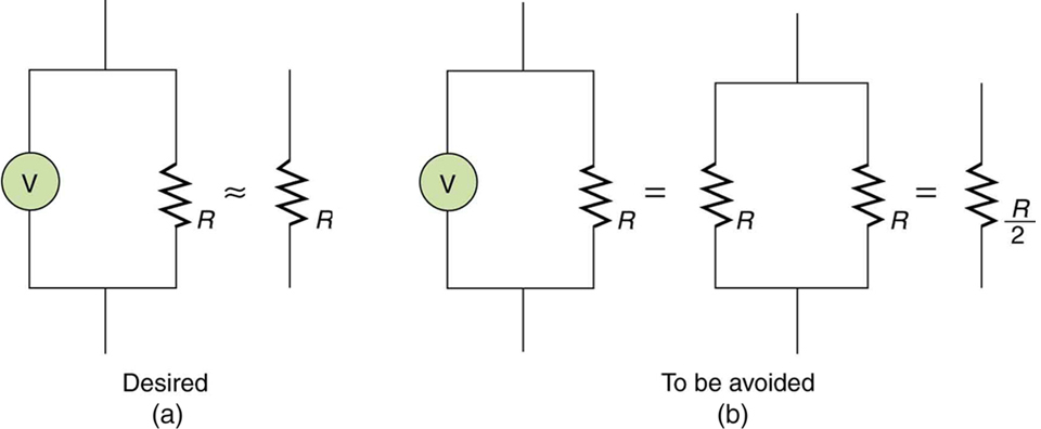
A voltmeter is placed in parallel with the voltage source to receive full voltage and must have a large resistance to limit its effect on the circuit.
. Describe the proper way to place the DMM leads and the steps you use to attain the most precise measurement value for voltage across components using a Digital Multimeter DMM. When placing the leads we had to make sure that we kept them still on the. Put it accross the components you are measuring.
It is measured in the unit of the Ampere simply called Amp A. The high resistance of the voltmeter combines with the impedance of the element across which it is connected. This is a video which demonstrates how to connect a voltmeter to measure potential difference across a resistor in a circuit.
A voltmeter is an instrument used for measuring the electrical potential difference between two points in an electric circuit. Try the different values for measuring voltage on your DMM. How to check a multimeters internal fuse.
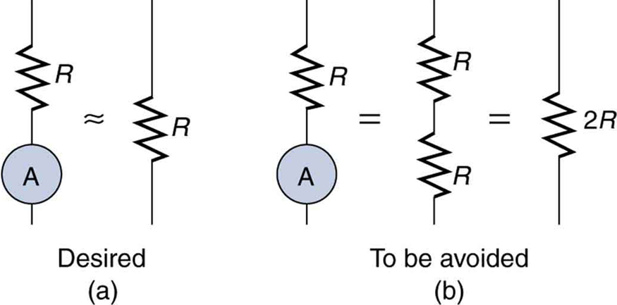
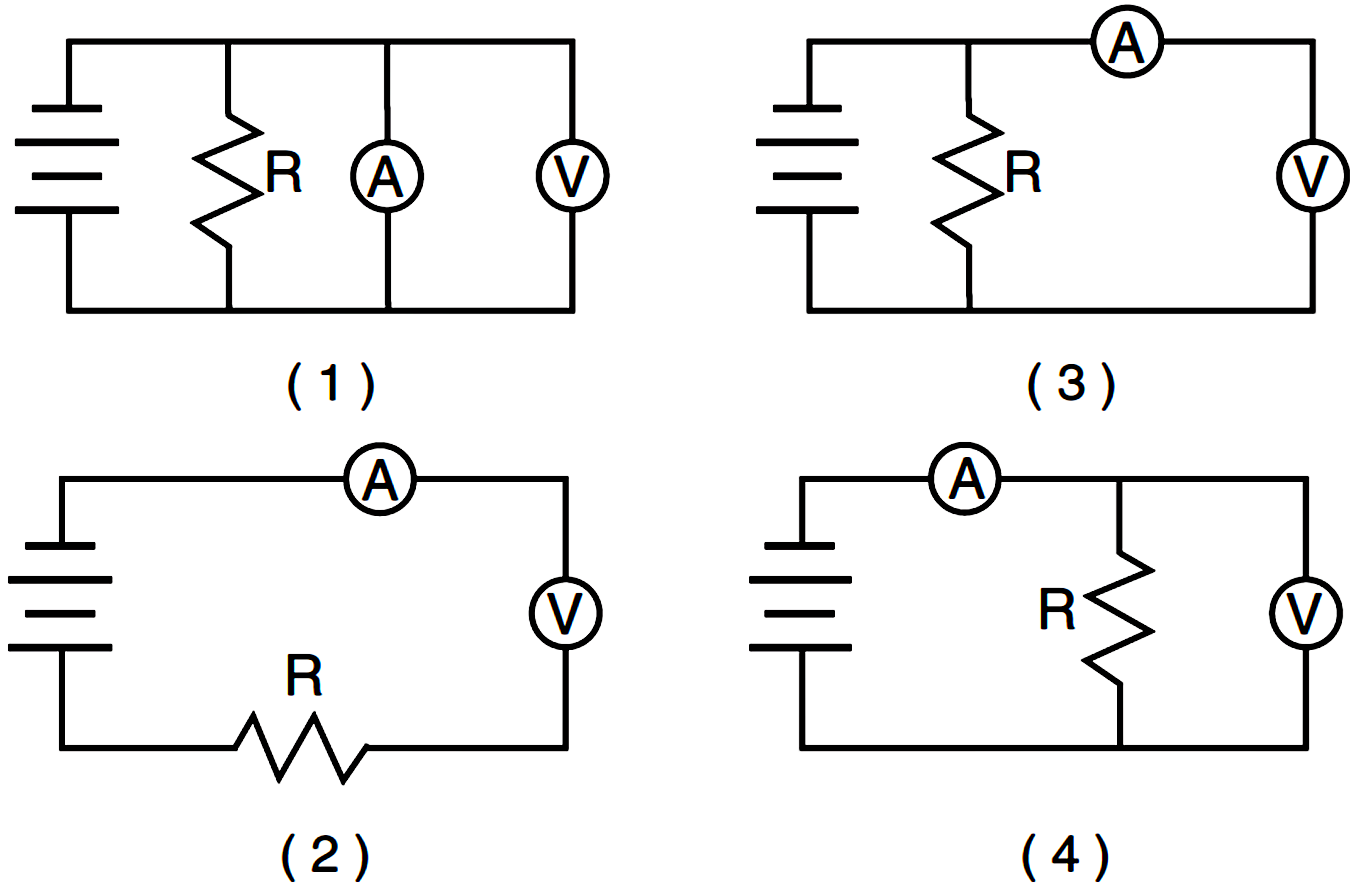
Selection of proper meter range Ammeter Schematic Diagram. An ideal voltmeter has infinite resistance. An ammeter is connected in series while a voltmeter is connected in parallel.
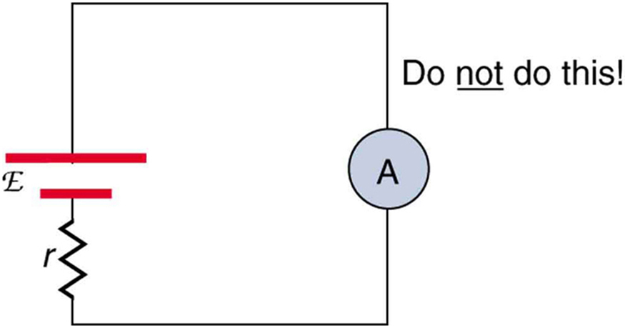
How to measure current with a multimeter. A voltmeter is connected in parallel to a circuit element because when connected in parallel it draws least current from the main current. As a result it must be connected in series so that as much current can pass through it as possible.
An ideal ammeter has almost negligible resistance. You want the smallest value that is larger than the actual. Describe the proper placement of a voltmeter in a circuit.
By definition aiding voltage sources add with one another to form the total voltage so we add 24 volts to -17 volts to obtain 7 volts. After doing some math the relative error is. I hope you like it.
Describe the proper placement of a voltmeter in a circuit. You must break the circuit and place the meter in series with the circuit andor component. Explain why a voltmeter must be connected in parallel with the circuit.
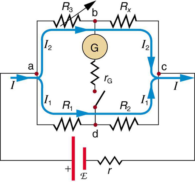
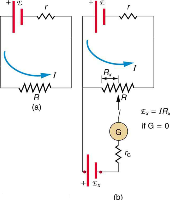
Find the resistance that must be placed in series with a galvanometer to allow it to be used as a voltmeter with a given reading. The voltmeter should be place parallel to the resistor. An ammeter is placed in series to get the full current flowing through a branch and must have a small.
With no voltmeter connected to the circuit there should be exactly 12 volts across each 250 MΩ resistor in the series circuit the two equal-value resistors dividing the total voltage 24 volts exactly in half. This may be used by learners to. Our multimeter is auto ranging so we didnt need to adjust the range when getting a precise measurement.
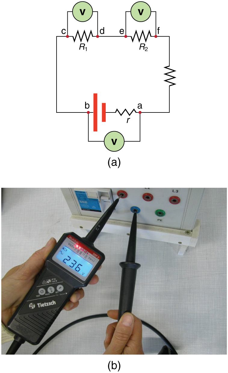
Describe how a galvanometer can be used as either a voltmeter or an ammeter. A To measure the potential difference in this series circuit the voltmeter V is placed in parallel with the voltage source or either of the resistors. Describe the proper way to place the DMM leads and the steps you use to attain the most precise measurement value for voltage across components using a Digital Multimeter DMM.
According to this diagram the polarity marks which indicate meter test lead placement indicate the sources aiding each other. If we let the polarity markings guide our decision to either add or subtract voltage figures -- whether. Since voltage drop is experienced in the resistor and the voltmeter will measure the voltage across the resistor.
The voltmeter always connects in parallel with the circuit so that the same voltage drop occurs across it. But when the voltmeter is used. The proper placement of a voltmeter in the circuit is across the resistor being measured.
And the overall impedance of the system is equal to the impedance that the element had. Prepare the circuit DC Source and Analog Multimeter. If we add the voltmeter in series then the voltage in the circuit in which it is connected drops.
Voltage is measured across a component but current flows through a component. The voltmeter is always connected in parallel in the circuit because the pressure coil used in the voltmeter is made of thin wire and high resistance. The ideal voltage under these conditions should be.
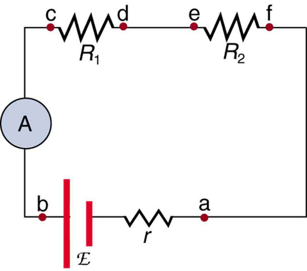
Draw a diagram showing an ammeter correctly connected in a circuit. Still the correct answer. A voltmeter is a high resistance galvanometer used to measure potential difference.
A voltmeter is an instrument used to measure the potential difference between the two ends of a current-carrying conductor. Note that terminal voltage is measured between points a and b. In this learning activity youll read the steps for proper meter placement for the measurement of resistance voltage and current.
To measure the potential difference between two points a voltmeter should be connected in parallel to the points. So it measures nearly accurate potential difference. However if the voltmeter in question has a lead-to-lead resistance of 10 MΩ a common amount for a modern digital voltmeter its resistance will create a parallel subcircuit.
If it is connected in parallel the circuit will be shorted and no current will pass through any electrical components connected in the circuit. Since the system is in series the total voltage of the resistors in the system is a summation of all the voltages across the resistor.
Electrical Meters

Homework And Exercises Wrong Positioned Ampere Meter And Voltmeter Physics Stack Exchange

18 2 Parallel Circuits Series And Parallel Circuits Siyavula

Correct Placement And Use Of Ammeter And Voltmeter Engenharia Eletrica Eletrica Engenharia
Dc Voltmeters And Ammeters College Physics
Voltmeters And Ammeters Boundless Physics
Dc Voltmeters And Ammeters College Physics
Electrical Meters
Voltmeters And Ammeters Boundless Physics
Dc Voltmeters And Ammeters College Physics

Electrical Meters

Voltmeters And Ammeters Boundless Physics

Ammeters And Voltmeters Ck 12 Foundation
Dc Voltmeters And Ammeters College Physics
Electrical Meters

Ammeter Vs Voltmeter Circuit Theory Doc Physics Youtube
Electrical Meters
Where Should An Ammeter Be Placed In A Parallel Circuit So That It Measures The Current Of A Specific Resistor Quora
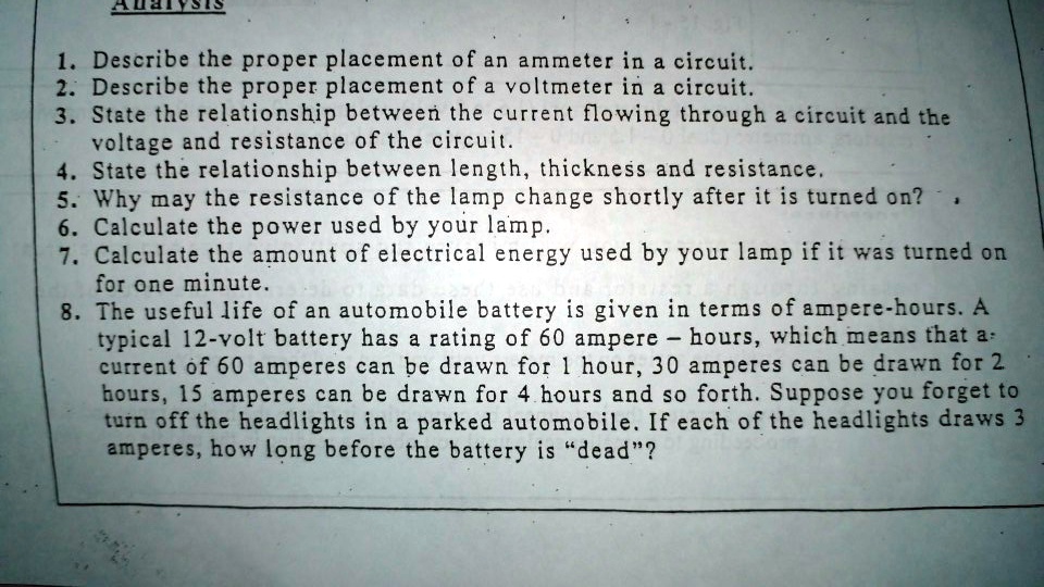
Solved 2uac Describe The Proper Placement Of An Ammeter In A Circuit 2 Describe The Proper Placement Of A Voltmeter In A Circuit 3 State The Relationship Between The Current Flowing Through


Comments
Post a Comment